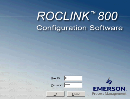
A great feature of ROCLINK 800 was the ability to find the TLPs with the software. Field Tools, however, does not have this ability, so we need a map to find out what the Logical Point is for the TLPs.
While ROCLINK 800 is still available to use with the FBx, you will have to ignore some errors as the ROCLINK 800 does not support some of the new features (https://www.scadacore.com/2015/04/23/roclink-800-viewing-numeric-representation-of-tlps/).
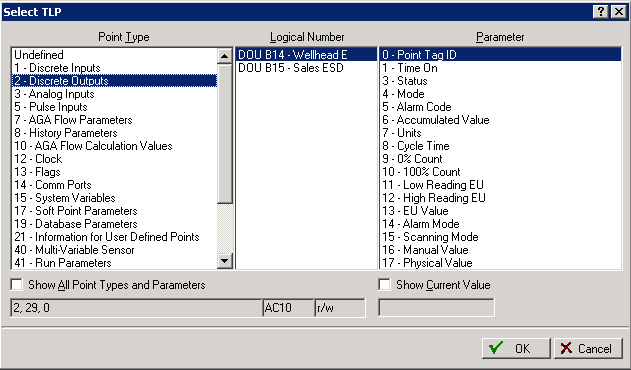
The mapping for the Extended I/O is as follows:
Digital Inputs Are from 19-28
Digital/Discrete Outputs are from 29-38
Pulse Inputs are from 39-48
Analog Inputs are from 3-10
Analog Outputs are from 11-18
It is important to note that the counting of the logical numbers are unaffected by the configuration. The I/O number is largely ignored when using ROC Protocol.
In the example below:
- PI1 = Logical 39
- DI1 = Logical 19
- DI2 = Logical 20
- DI3 = Logical 21
- D01 = Logical 29
- D02 = Logical 30
Analog
- Ain1 = Logical 3
- Ain2 = Logical 4
- Ain3 = Logical 5
- Ain4 = Logical 6
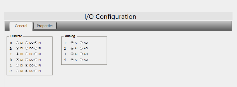
As shown in the example, the Discrete Number or Analog Number that is listed in Field Tools is ignored. The first I/O of a specific type you use is considered the first in the logical number.
